I will grab the opportunity from my last post regarding multiple strokes and fills,
and I will explain in detail the Stroke Panel and its functions. You
use the Stroke panel to control whether a line is solid or dashed, the
dash sequence if it is dashed, the stroke weight, the stroke alignment,
the miter limit, and the styles of line joins and line caps. So let's
see all that in detail.
Start Illustrator and have a look
on the right dock. Locate the Stroke Panel, click to open it and expand
it by clicking on the small two-sided arrow symbol, so we can see the
rest of the settings available.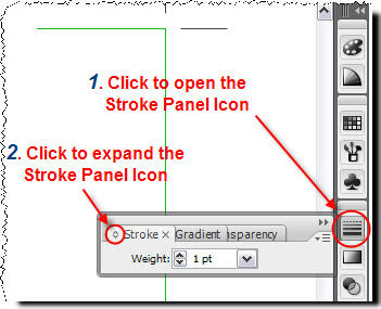
Small Tip:
Alternatively go to Top Menu, Window > Stroke.
Now
you should be able to see the fully expanded Stroke Panel. For
demonstration reasons I've divided the panel in 5 areas. So, let's see
what each section does.
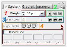
1. Adjust the width of the stroke.
Quite
straight forward. Select your path, just enter a value in the box (or
just click the arrows) and you adjust the thickness of the stroke.
So start Illustrator, create a new document and draw a straight path using the pen tool  (or any other tool you prefer) so that we can experiment with. Try creating something like that.
 (or any other tool you prefer) so that we can experiment with. Try creating something like that.
 The larger the value, the thicker the stroke.
Note
Please
keep in mind that in all the above cases, the path looks the same . If
you select View > Outline (or just click CTRL+Y) from the Menu bar,
you shall see that in all four cases the path is identical.

Ok, let's return to Preview Mode and move forward. Select View > Preview (or just click CTRL+Y) from the Menu bar.
2. Change the cap style of a line.
A cap
is the end of an open line. You can change the caps of a line by
changing the object’s stroke attributes. In the following image you may
see the different result of each selection.
 The Round Cap creates stroked lines with semicircular ends.
 The Projecting Cap
creates stroked lines with squared ends that extend half the line width
beyond the end of the line. This option makes the weight of the line
extend equally in all directions around the line.
 3. Change the joins of a line.
A join
is where a straight line changes direction (turns a corner). You can
change the joins of a line by changing the object’s stroke attributes.
 The Round Join creates stroked lines with rounded corners. Have a look below:
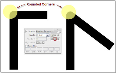
 The Bevel Join creates stroked lines with squared corners. Have a look below:
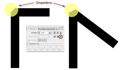
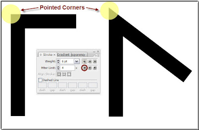
Let me explain to you now what is the Miter Limit. You can consider the Miter limit as a threshold above which a pointy 'sharp' corner is transformed to a bevel. How is this threshold defined? Have a look at the following illustration. There is a 6pt stroked line and I have set the Miter Limit to 5. This means 5 times the line thickness (6 X 5 = 30 pts). So If the Mitter Length - 'the corner head' (the overlapping common area of the two segments that form the corner) - is more than 5 times the stroke thickness of the path, then the corner will be beveled.
Here is an example.
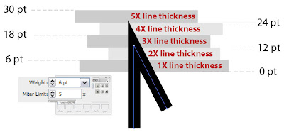 On
the above image, you see that the arrow head length barely exceeds
24pts, this is a bit more than 4 times the line thickness. Since the
limit is 5 and we stay below, the sharp Miter Join is maintained.
Ok, now I have reduced the Miter Limit
to 4 times the line thickness of the segment. See what has happened. My
nice sharp and pointy corner has been replaced by a chamfer. The limit
has been violated, therefore the Miter Join is now replaced replaced by a Bevel Join.
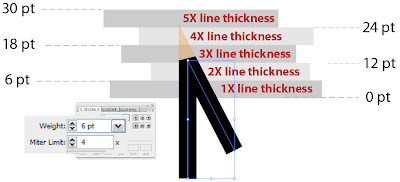
The Miter Limit controls when the program switches from a mitered (pointed) join to a beveled (squared-off) join.
4. Align the stroke along the path.
This option is only available in closed paths. So, let's draw a rectangle as shown below so that we explore all three options.
a. Align Stroke To Center
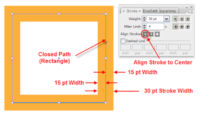 As you see, the stroke is symmetrically aligned to the center of the path.
b. Align Stroke To Inside
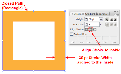 In this case, the stroke is aligned to the inside of the path.
c. Align Stroke to Outside
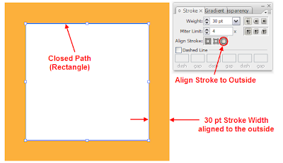 Here, the 30 pt amber stoke is aligned along the path to the outside area.
Note:
Be
cautious when you try to align objects, to use the same stroke
alignment settings, otherwise you will not be able to achieve perfect
match and alignment.
5. Create a dotted or dashed line.
This is a handy tool that helps you quickly draw dotted lines or dashed lines. Let me show you how.
Draw a straight path segment so we can experiment with.
 Select the line and in the Stroke panel, check the Dashed Line checkbox. You can specify
a dash sequence by entering the lengths of dashes and the gaps between
them. I have used a sequence consisting of 5pt dashes and 20pt gaps. So
just input these values in the first two boxes as shown below.
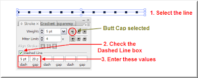
The
numbers entered are repeated in sequence so that once you have
established the pattern, you don’t need to fill in all the text boxes.
The square-ended dashes result from the Butt Cap setting being selected. Select the line and toggle between the Butt Cap, the Round Cap and the Projecting Cap line ends and see what happens.

As you would have probably guessed, the Round Cap  option creates rounded dashes or dots and the Projecting Cap
  option extends the ends of dashes.
Try
playing around with the values in the dash size and gap size and
produce really nice patterns. For example if you input the values shown
in the following image, you will end up with a nice dotted line.
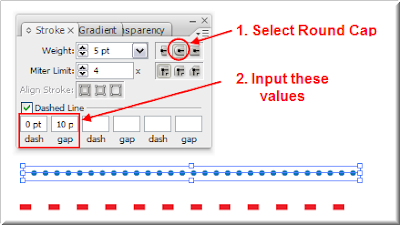
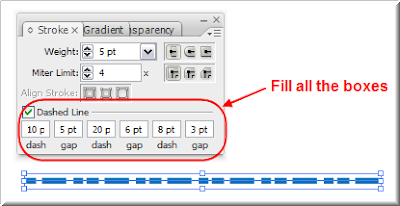
Finally, you can create completely custom line patterns by filling all the values. For example, have a look at the following image. If you enter the values shown you will get the following nice interesting line pattern.
That's all folks...


0 comments :
Post a Comment